
Featured Precision Engineered Components
Explore our tier-1 manufactured OEM metal injection molding components designed with tight tolerance controls for critical global supply chains.
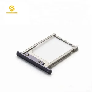
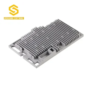
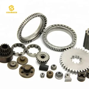
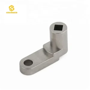
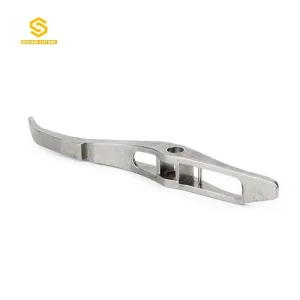
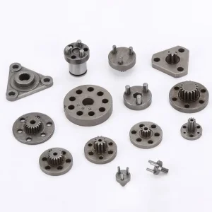
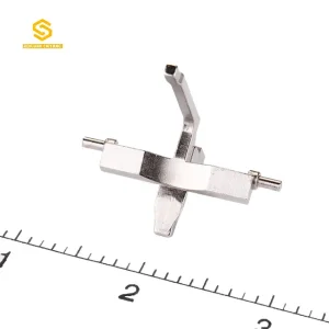
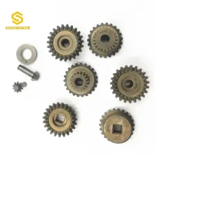
Wholesale High Precision 304 Stainless Steel Parts China Metal Fabrication
View Product Specifications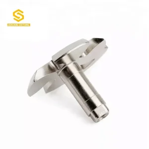
1. Executive Overview & The Physical Principles of MIM Tolerances
Understanding the complex thermodynamics and rheological behaviors that determine dimensional consistency in Metal Injection Molding (MIM).
Metal Injection Molding (MIM) has emerged as an indispensable net-shape manufacturing process for small, intricate, high-precision metal components. Combining the design flexibility of plastic injection molding with the structural strength of wrought alloys, MIM enables mass production of geometries that would be cost-prohibitive or physically impossible to machine via traditional 5-axis CNC equipment. However, achieving precise MIM tolerances requires a deep mastery of physical phenomena occurring across feedstock preparation, injection molding, debinding, and thermal sintering.
Rheology & Homogeneity
The volumetric ratio of metallic powder (typically 0.5–15 µm spherical particles) to thermoplastic binder systems directly governs green-part consistency. Variations in solids loading exceeding ±0.2% can lead to dimensional shifts across the batch.
Volumetric Sintering Shrinkage
During high-temperature sintering (1200°C–1380°C depending on alloy), the component undergoes linear shrinkage of 12% to 22% (volumetric shrinkage up to 50%). Controlling isotropic shrinkage requires uniform thermal distribution within vacuum furnaces.
Gravity & Friction Friction (Drag)
As the brown part densifies, friction between the component base and ceramic sintering setters induces thermal drag. Uncompensated drag results in distortion, taper, and loss of perpendicularity across vertical axes.
2. Comprehensive MIM Tolerances Technical Matrix & GD&T Guidelines
Industry-standard versus precision tolerances achievable through engineering controls, sizing, coining, and post-machining processes.
| Dimensional / Geometric Feature | Standard MIM As-Sintered | Precision MIM (Optimized DFM) | Secondary Sizing / CNC Machined |
|---|---|---|---|
| Linear Dimensions (< 10 mm) | ±0.030 mm (±0.3%) | ±0.015 mm (±0.15%) | ±0.005 mm |
| Linear Dimensions (10 mm - 50 mm) | ±0.3% of nominal size | ±0.1% to ±0.2% | ±0.008 mm |
| Flatness / Warpage (per 25 mm span) | ±0.050 mm | ±0.025 mm | ±0.005 mm (Lap Ground) |
| Hole Diameter (As-Molded Core Pins) | ±0.3% | ±0.15% | ±0.004 mm (Reamed/Bored) |
| Hole Center Distance (CD) | ±0.050 mm | ±0.025 mm | ±0.005 mm |
| Concentricity & Ovality | 0.08 mm TIR | 0.04 mm TIR | 0.005 mm TIR |
| Surface Roughness (Ra) | 1.0 µm - 1.6 µm | 0.6 µm - 0.8 µm | 0.1 µm - 0.4 µm (Polished) |
| Density (% Theoretical) | 95.5% - 97.0% | 97.5% - 98.5% | 99.5%+ (with HIP Post-Treatment) |
GD&T Optimization Rules for Sintering
To preserve tight geometric tolerances without mandatory secondary machining, component designers must incorporate structural symmetry, generous fillet radii (minimum 0.4mm), uniform wall thickness (ideally 1.0mm to 3.0mm), and flat landing surfaces for sintering setters.
Material Shrink Factor Control (CPK ≥ 1.33)
By enforcing Statistical Process Control (SPC) across feedstock blending and utilizing automated optical sorters, leading manufacturers achieve process capability indices (CPK) exceeding 1.33 on critical dimensions across million-piece annual production runs.
3. Global Procurement Demands & Industrial Application Solutions
How OEM procurement leaders leverage high-precision MIM manufacturing to resolve weight, cost, and assembly bottlenecks across key industries.
Automotive Industry (IATF 16949)
High-stress drivetrain parts, variable valve timing (VVT) rotors, turbocharger vanes, and seat belt latch mechanisms require mechanical tensile strengths exceeding 1000 MPa (using heat-treated 17-4PH or 4605 steel) combined with ±0.2% strict tolerance stability.
Medical & Surgical Devices
Laparoscopic surgical jaws, endoscopic staplers, and dental orthodontic brackets demand biocompatible 316L or titanium alloy (Ti-6Al-4V) components. Micro-MIM capabilities allow feature resolution down to 0.1mm with surface roughness suitable for passivation.
Consumer Electronics
Foldable smartphone hinges, smart watch frames, fiber optic connectors, and camera rings require cosmetic perfection alongside high structural rigidity. MIM allows mass manufacture of thin-walled (0.6mm) structures with zero internal porosity.
Aerospace & Defense
Weight reduction via topology optimization combined with nickel superalloys (Inconel 718/625) allows defense OEMs to consolidate multi-part assemblies into single, monolithic MIM components, drastically mitigating supplier risk.
4. Technical Roadmap & Future Outlook in MIM Tolerance Control
Innovations driving next-generation metal injection molding precision and feedstock performance over the coming decade.
AI-Driven Thermal Modeling
Integrating machine learning algorithms and finite element analysis (FEA) to simulate sintering shrinkage dynamically. Predicts non-linear sagging and drag distortion prior to mold construction, cutting tool iteration cycles by 60%.
Multi-Material 2K MIM Co-Sintering
Simultaneous injection of two distinct metal powders (e.g., magnetic soft iron combined with stainless steel). Offers multi-functional components with seamless metallurgical bonding and unified tight tolerances.
Nano-Powder & Ultra-Fine Feedstocks
Transitioning from standard 10-15 µm powders to sub-micron particle sizes. Increases sintered density to >99%, reduces sintering thermal windows, and improves as-sintered surface finishes to below Ra 0.4 µm.
5. Global Industrial Status & Supply Chain Integration
Navigating international supply chain economics, Near-Net-Shape (NNS) material efficiency, and total cost of ownership (TCO).
The global Metal Injection Molding market is experiencing unprecedented expansion driven by demand for miniaturization in automotive electrification and medical robotics. China has established itself as a premier global hub for high-capacity MIM manufacturing, combining cost-competitive tooling production with world-class metallurgical engineering.
When evaluated against traditional manufacturing routes, MIM provides significant commercial advantages for complex parts produced at quantities exceeding 5,000 units annually:
MIM vs. 5-Axis CNC Machining
While CNC machining incurs exponential cost escalations as feature complexity increases, MIM component costs remain virtually flat regardless of geometric intricacy. Material utilization rates increase from 20% (machining scrap) to over 95% in MIM.
MIM vs. Investment Casting
Investment casting suffers from coarse surface finishes (Ra 3.2-6.3 µm) and wide dimensional tolerances (±0.5% to ±1.0%). MIM offers vastly superior surface quality, finer grain structures, thinner wall capabilities, and twice the dimensional accuracy.
MIM vs. Conventional Press & Sinter PM
Conventional powder metallurgy is restricted to 2.5D shapes pressed along a single axis. MIM enables true 3D geometric freedom—including undercuts, cross-holes, internal threads, and intricate logo embossing—with higher final mechanical density.
6. Localized Technical Support, Quality Assurance & Compliance
End-to-end quality validation protocols ensuring absolute adherence to international client technical drawings.
Advanced Metrology Laboratory
Our facilities are equipped with Zeiss 3D Coordinate Measuring Machines (CMM), Keyence optical profile projectors, X-ray computed tomography (CT) for internal void detection, and metallographic micro-hardness testers.
Global Compliance & Documentation
Full documentation packages supplied with production lots, including PPAP Level 3, Material Test Reports (MTR) according to EN 10204 3.1, RoHS/REACH compliance certifications, and conflict-free mineral disclosures.
Dedicated Engineering Liaison
Our fluent English engineering staff provides direct DFM consulting, non-disclosure agreement (NDA) execution, custom packaging design, and DDP/FOB logistics assistance tailored to North American and European buyers.
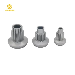
Additional OEM Precision Manufacturing Solutions
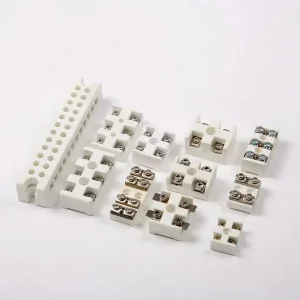
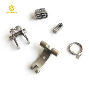
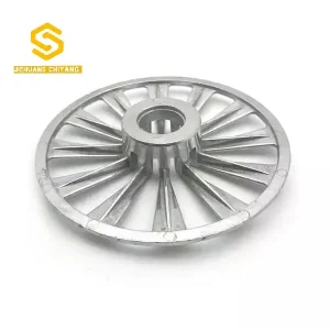
Explore our expanded powder metallurgy, die casting, and CNC machining component offerings available for direct wholesale supply.
7. Frequently Asked Questions (FAQ) on Metal Injection Molding Tolerances
Authoritative engineering responses to key procurement and technical inquiries regarding MIM tolerances and process capabilities.
What is the standard tolerance capability for as-sintered MIM components?
The global standard as-sintered linear tolerance for Metal Injection Molding is ±0.3% to ±0.5% of nominal dimensions. For example, a 10 mm dimension typically achieves a tolerance of ±0.03 mm without secondary operations. With optimized Design for Manufacturability (DFM) and tight feedstock powder controls, precision MIM can reach ±0.15% to ±0.2% on critical features.
How are micro-tolerances tighter than ±0.1% achieved in MIM manufacturing?
When application requirements exceed standard sintering limits (e.g., tight bearing seats or hydraulic valve spools requiring ±0.005 mm tolerances), post-sintering operations are integrated. These include mechanical coining/sizing dies, CNC thread chasing, grinding, reaming, or wire EDM machining on pre-defined tool pad areas.
Why do MIM parts shrink during manufacturing, and how is shrinkage calculated?
MIM components shrink by 12% to 22% linearly (up to 50% by volume) during thermal sintering because the binder matrix (typically 35-45 vol%) is extracted, allowing fine metal particles to fuse via solid-state diffusion. Shrinkage factors are calculated using precise feedstock density formulas: Shrinkage Factor = 1 - (Green Density / Sintered Density)^(1/3). Tool cavities are oversized precisely according to this factor.
What physical limitations impact geometric tolerances (GD&T) in MIM?
The main physical limitations include thermal drag friction against sintering setters (affecting flatness and perpendicularity), wall thickness variations (causing uneven thermal mass and localized warpage), and gravity-induced sagging on unsupported overhangs. Incorporating ceramic setter fixtures and uniform wall design rules mitigates these issues.
Which metal alloys offer the best dimensional consistency in MIM production?
Austenitic stainless steels (316L) and precipitation-hardening stainless steels (17-4PH) exhibit exceptionally predictable sintering behavior and grain boundary control, offering superior dimensional stability. Low-alloy steels (Fe-2Ni, 4605) and titanium alloys (Ti-6Al-4V) also yield high consistency when processed under tightly controlled vacuum sintering atmospheres.
What quality inspection equipment is required to validate MIM tolerance compliance?
A fully qualified MIM Quality Control laboratory utilizes automated 3D CMM machines, multi-sensor optical measuring systems, laser scanners for full-field surface warpage mapping, metallographic micro-structure analyzers, and density testing equipment complying with ASTM B883 standards.